Oshigata · documentation method · 反射撮影
The Dome
A reflectance-imaging station for reading worn and rusted mei, and — more often — for capturing the low relief of tōsōgu: nanako grounds, kebori line, takabori undercut, iroe edges. The signature-reading problem is what started it; the fittings are the larger use.
What it is
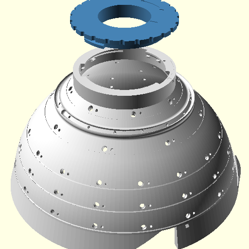
Reflectance transformation imaging photographs a fixed subject once per light, from a fixed camera, with a single small source stepping through a known set of directions. The stack of frames solves into a per-pixel surface model you can then relight from any angle in software — which is how a signature too shallow and too corroded to read under a loupe resolves the moment light rakes it from the right side. The instrument exists for grazing light; everything about the geometry serves putting lights low and knowing exactly where they are.
The shell
280 mm across, a 5 mm wall, printed in one piece, rim down. A sphere is self-supporting only while its surface stays above 45° from horizontal, so the shell is a sphere to 45° elevation and a 45° cone the rest of the way to the zenith — the sphere's own tangent at 45° is 45°, so the join is seamless and everything above it prints at the limit. The bottom is open: it sits over the subject like a cover, and the blade lies flat on the bench in its natural repose. One chord-cut opening leaves a single vertical fence wall that the mune registers against, so blade clocking is set by geometry rather than by eye.
The lights
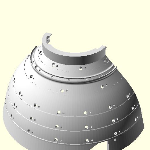
Five rings, weighted low: sixty-four lights on a common 22.5° azimuth grid — three sixteen-light rings on the sphere at 15°, 25°, and 35°, and two eight-light rings on the cone at 50° and 65°. Three-quarters of the lights sit at or below 35°, because grazing coverage is the one thing that can ruin a dataset while absolute placement barely matters — two millimetres on a 140 mm radius is under a degree. They are discrete 5 mm LEDs in printed sockets counterbored to aim at the origin, not addressable strip, whose pitch is finer than the sampling wants and whose flicker beats against the shutter.
The load-bearing idea is that the ring table in the model is the single source of truth: the same table emits the geometry and the light-position file, so design and calibration cannot drift apart. The file holds directions, not positions — which is why the dome could be rescaled and given a conical cap without the calibration changing by a byte.
The camera bayonet
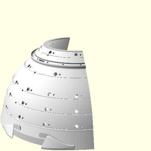
Swappable plates drop into a keyed bayonet at the zenith: three lugs at 0, 100, and 210° admit the plate at exactly one clocking, and a hard stop 45° round takes out the entry slop so the final orientation is set by contact, not by feel. That matters because the calibration silently assumes the camera's frame is aligned to the light grid — a consistent clocking error is harmless and gets absorbed, but variation between captures is the worst failure mode there is. The plate's top disc lands flat on the flange, gravity-seated and helped by the camera's own weight, so working distance doesn't depend on any screw.
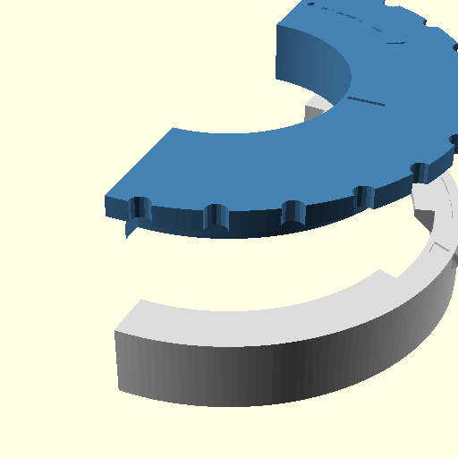
Printing it
One piece, rim down, no supports — about 800 g and forty hours. Everything that could ruin that print gets printed small first, in the same orientation, because half these features only behave the way they do because of which way up they are: a coupon for the LED-bore fit, a collar for the bayonet, a wedge for the wiring pull, a tray for the control board. The interior is matte black throughout — interreflection matters more than expected on steel, and the printed layer lines, left unsanded, spread whatever specular survives up and down the meridian instead of bouncing it back as a point.
Parts
As an Amazon Associate I earn from qualifying purchases. These are the parts actually on the bench; the links are a convenience and name what I used, not a recommendation of any particular brand.
- Musou Black
- The interior coating. Its ~0.6% residual reflectance is what lets the mirror-sphere calibration measure geometry instead of geometry plus an ambient term. Two 100 ml bottles cover the inside of one dome with margin.
- Silicon-carbide reference spheres
- Half-inch precision ceramic balls. The specular highlight on a mirror sphere is how each light's true direction is recovered and the designed values overwritten with measured ones — the calibration target the whole instrument is built around.
- Diffused 5 mm LEDs
- Wide-angle diffused beats water-clear here: a narrow lens throws a hot centre the fitters then have to model as surface behaviour. They must all come from one bin. Three I'm weighing — EDGELEC diffused white, CHANZON warm-white straw-hat, and CHANZON white straw-hat.
- Creality Hyper PLA, black
- The print stock. The dome alone is most of a 2 kg spool; the 4 kg bundle covers the test sections too.
- The printer
- The dome's 290 mm footprint needs a 300 mm bed or bigger, and fits one only just. I print on the Creality K1 Max (300 mm bed, CoreXY, fast); the K2 Plus (350 mm) gives room to spare.
- Raspberry Pi 5 kit
- Runs the sequencer — sixteen anode switches and five cathode sinks off one shared constant-current source, stepping the sixty-four lights with a settle delay and a shutter trigger.
Files
The model is parametric OpenSCAD, and the light-position file is emitted from the same ring table, so calibration and geometry stay locked together. Print the small test sections first, in the same orientation as the dome — the coupon and collar cost an evening and retire the two fits that would otherwise be found out forty hours in. Print files aren't posted here yet; the geometry is still settling against test prints.